Walking Beam Quenching and Tempering Production Line for Oil Well Pipes Factory: A Complete Process Overview
2026-09-13
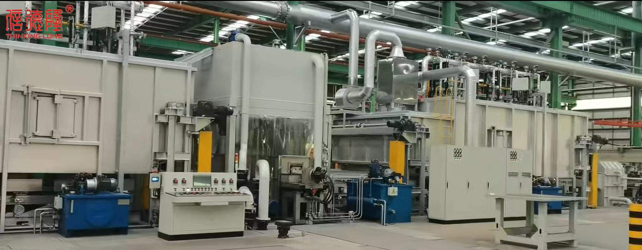
Watch a length of oil well casing move steadily through a walking beam furnace—heat, quench, temper—and you're seeing the difference between a pipe that survives decades downhole and one that fails early. That reliability is exactly what a walking beam quenching and tempering production line is designed to deliver. The complete process overview from THINKING-LONG reveals how uniform austenitizing, controlled quenching, and final tempering lock full-length mechanical properties into every oil well pipe, batch after batch.
Why Walking Beam Motion Keeps Pipe Temperature Uniform
Walking beam transport works by lifting the pipe off the stationary supports, moving it forward a set distance, and lowering it onto a new position before the beam returns. This repeated lift-and-advance sequence changes the points where the pipe touches the furnace supports on every cycle. Since no part of the circumference stays in continuous contact with a cooler beam or skid, heat reaches the full surface more evenly. Localized cold spots from contact shading are largely avoided.
The motion also creates a brief gap between pipe and support during each transfer. Hot furnace gases circulate through that gap and around the pipe, helping equalize temperature along the length and across the wall thickness. In addition, because the walking beam indexes all pipes forward at once with controlled spacing, adjacent pipes do not permanently shield one another from radiant heat. The result is a more consistent thermal profile than a fixed-position or roll-hearth setup would typically deliver.
Operators can adjust the beam cycle speed and stroke to match the pipe diameter and wall thickness. Slower cycles give more exposure time, while shorter strokes reduce the distance between contact points. This control over the heating rhythm is what makes walking beam furnaces especially useful for alloy pipes that are sensitive to uneven heat, where even small temperature differences can affect mechanical properties after quenching or tempering.
Quenching Intensity Control for Deeper Wall Hardening
Achieving deeper wall hardening is not just a matter of increasing quench severity across the board. It requires mapping the cooling curve to the specific steel grade and section thickness. Overly aggressive quenching may harden the surface but leaves the core too brittle or triggers distortion. Instead, the goal is to sustain a cooling rate above the critical transformation threshold long enough for the thermal wave to penetrate the wall. This often means moderating the initial vapor blanket stage while extending the nucleate boiling phase, which extracts heat more uniformly from subsurface layers.
Practical control hinges on selecting the right quenchant and delivery method. For many medium-carbon and low-alloy steels, polymer solutions offer a useful middle ground because their concentration can be tuned to adjust the cooling curve without the abrupt shock of brine or the slow tail of plain oil. Spray quenching gives another lever: nozzle positioning, pressure, and flow rate can be varied across the part to compensate for geometric shadowing. In thick-walled components, interrupted quenching or time-controlled immersion often proves more effective than simply raising agitation speed, because it prevents the surface from cooling too far ahead of the interior.
On the shop floor, this translates into monitoring quench bath temperature, agitation patterns, and even real-time hardness sampling from test coupons. Small adjustments, such as raising bath temperature by ten degrees or changing the polymer ratio by a few percent, can shift the effective case depth by several millimeters. The most consistent results come from treating quench intensity as a dynamic variable, not a fixed parameter. When deeper wall hardening is required, the process should be tuned iteratively against actual section thickness and prior microstructure, rather than relying on a standard recipe.
Tempering Parameters That Improve Sulfide Stress Resistance
For quenched low-alloy steels, the tempering temperature has a direct effect on sulfide stress cracking behavior. Holding the tempering cycle above about 620°C—most often between 660°C and 690°C—brings hardness below the 22 HRC limit commonly accepted for sour service. Softer tempered martensite reduces residual stresses and lowers the steel's sensitivity to hydrogen-assisted failure. By contrast, tempering below 500°C can leave the part in a hardness range where sulfide stress cracks start more easily, so those lower temperatures are usually avoided unless other controls are in place.
Tempering time and cycle count matter just as much as the peak temperature. A single short soak may not fully transform retained austenite or spheroidize carbides, leaving local hard zones that act as initiation sites. Double tempering, with intermediate cooling to room temperature, helps convert retained austenite and produces a more uniform microstructure. The second cycle also allows any fresh martensite formed during cooling to be tempered, which is particularly important for grades with higher carbon or alloy content.
Cooling rate after tempering is sometimes ignored, but it deserves attention. Slow cooling through roughly 450–600°C gives impurities like phosphorus, antimony, and tin time to migrate to prior austenite grain boundaries. That segregation weakens the boundaries and increases sulfide stress cracking susceptibility even when bulk hardness looks acceptable. A faster cool from the tempering temperature—air for smaller parts, a controlled air blast or oil for heavier sections—suppresses this reversible temper embrittlement and helps keep the improved resistance from the high-temperature soak intact.
Minimizing Contact Marks Through Beam Design Adjustments
Reducing visible contact marks on molded parts often starts with rethinking how the beam enters the cavity. Instead of relying on a single, straight injection path that concentrates pressure at one point, designers can introduce a slight curvature or stepped profile along the beam's length. This subtle geometry change redistributes the melt flow more evenly, lowering peak shear stress at the gate area and preventing the characteristic blush or halo that appears when hot material rushes against a cold mold wall. A curved beam also encourages a more gradual pressure drop, which helps the part release cleanly without dragging against the core.
Another practical adjustment involves shifting the gate location away from the most visible surface. By moving the entry point to a rib or an interior boss that gets hidden after assembly, any residual mark becomes functionally invisible. Pairing this with a wider but shallower beam cross-section allows the material to spread laterally upon entry, creating a fan-like flow that breaks up the direct impingement pattern. The result is a smoother transition zone with no distinct ring or dot, even when using glass-filled or high-viscosity resins that tend to show flow lines more readily.
For parts where the beam must remain straight due to load-bearing requirements, a two-stage injection profile can minimize contact marks without altering the geometry. Starting with a slower fill speed for the first few millimeters of beam length lets the melt establish a cushion against the cavity surface before the main volume arrives. This prevents the initial jetting effect that often leaves a snake-like trail. Once the beam is partially filled, the speed ramps up to complete the shot, maintaining dimensional stability while erasing the high-pressure footprint at the gate. Combined with a slightly elevated mold temperature near the beam's entry zone, this approach yields a clean, uniform surface with no post-machining required.
Inline Inspection Points Between Quench and Temper
Placing inspection stations directly after quenching and before tempering catches defects while correction is still practical. A quick hardness check or surface crack scan at this stage prevents flawed parts from consuming tempering furnace time and energy. Modern lines often position automated testers right after the wash station, feeding results into the control system within seconds.
Common checks include surface hardness, dimensional stability, and non-destructive testing for quench cracks. Eddy current and ultrasonic methods work well here because they are fast and can be integrated into conveyor-based handling. The data gathered isn't just for sorting scrap; it also helps fine-tune quench intensity or agitation, creating a feedback loop that reduces future defects.
Sensor placement matters. The area between quench and temper can be hot, wet, or oily, so shielding and temperature compensation are necessary. Most facilities pick a spot after post-quench washing but before the tempering furnace entry, where parts are cool enough for reliable readings. Linking the inspection unit to the material tracking system ensures that only accepted parts move forward.
Line Speed and Energy Use Across Different Pipe Sizes
For a given volumetric flow, pipe diameter sets the velocity. A DN100 line moving 100 m³/h runs at about 3.5 m/s, while a DN150 line drops that to 1.6 m/s. That difference feeds straight into friction loss: the smaller pipe might lose 40 metres of head per kilometre, the larger one under 8 metres. Since pump power tracks head times flow, you can be spending several times more electricity just by choosing the next size down.
Energy use does not scale linearly with speed. Doubling velocity roughly quadruples frictional loss in turbulent flow, which is why a modest reduction in line speed can cut pump energy sharply. But oversizing has its own cost: larger pipes hold more fluid, take longer to heat or cool, and can create low-velocity zones where solids settle or corrosion accelerates. In practice, many liquid systems aim for 1.5–3 m/s and gas systems for 15–30 m/s, but those ranges bend when the fluid is abrasive, viscous, or expensive to keep hot.
Whether a bigger pipe pays off depends on how often the line runs at full flow. A plant that moves product 24/7 will often find that a DN150 line pays back its extra material cost within a few years through lower pump energy. Intermittent lines, or those with long turndown periods, may be better off with a smaller diameter to avoid stagnant pockets and unnecessary thermal losses. Comparing total cost over ten years usually settles the argument faster than a velocity table.
FAQ
It's an automated line that uses a walking beam conveyor to move oil well pipes step by step through heating, quenching, and tempering. Each pipe is lifted, advanced, and lowered in a controlled cycle, which keeps spacing uniform and exposure even.
The walking beam lifts pipes rather than dragging them, so surface damage is minimal. It also keeps long pipes from banging into each other or rolling, which helps prevent bowing and ensures each pipe gets the same quench contact.
Most operations use water or a polymer quench because these grades need fast cooling to form martensite. Oil is sometimes selected for alloy pipes that are prone to cracking or distortion, but it requires more careful handling and cleaning.
Tempering brings the hardness down to a useful level and restores toughness. Without it, the as-quenched martensite would be too brittle for oil well service, where pipes face high pressure, thermal cycling, and mechanical shock.
The line is configured with adjustable walking beam pitch, programmable furnace zones, and movable quench headers. A change in pipe size usually means loading a different recipe rather than doing a major mechanical overhaul.
Process data like zone temperatures, quench flow, and walking speed are continuously logged. Frequent hardness checks, ultrasonic scans, and dimensional verification are carried out on samples or in-line to catch any deviation before pipes move to finishing.
Compared with batch furnaces, this continuous walking beam approach gives higher throughput and more uniform properties because each pipe follows the same thermal path. It needs less manual labor, reduces contact damage from stacking, and typically uses energy more efficiently.
The main concerns are hot surfaces, steam from quench tanks, and potential gas leaks in the furnace. Interlocked guards, emergency stops, water level controls, and regular inspections are essential. Operators also need clear procedures for startup, shutdown, and upset conditions.
Conclusion
Walking beam quenching and tempering lines for oil well pipe manufacturing rely on a carefully choreographed thermal cycle to meet API and sour-service requirements. The walking beam motion itself keeps each pipe moving through the furnace with a slight rocking advance, preventing prolonged contact with any single support point and evening out temperature profiles along the length and circumference. Once the pipe reaches uniform austenitizing temperature, quenching intensity is modulated through water flow, pressure, and spray pattern adjustments so that even thicker walls achieve the necessary martensitic transformation depth. After quenching, tempering parameters—particularly peak temperature and soak time—are selected to reduce residual stresses and improve sulfide stress cracking resistance, which is critical for pipes exposed to hydrogen sulfide in downhole environments.
Beyond thermal treatment, the line incorporates practical design features that directly affect product quality and operating cost. Beam shape and contact geometry are adjusted to minimize skid marks or localized soft spots that could compromise pipe integrity. Inline inspection stations positioned between the quench and temper units record hardness, straightness, and dimensional data before the second heating stage, allowing operators to intercept off-spec material early instead of discovering problems after final processing. Line speed and energy consumption are also tuned according to pipe diameter and wall thickness: smaller, lighter pipes can move faster with lower furnace setpoints, while larger, heavy-wall products require slower travel and higher heat input. These adjustments keep the overall process stable without wasting fuel or time, making the walking beam line a flexible solution for a range of oil well pipe sizes and grades.
Contact Us
Contact Person: Qian Xijun
Email: [email protected]
Tel/WhatsApp: 8613961736750
Website: https://www.thinkinglong.com/