
High-Quality PM Fiber Fusion Splicer: Achieving Perfect Alignment for Optimal Polarization-Maintaining Performance
2026-08-07
When it comes to polarization-maintaining (PM) fiber splicing, even a micron of misalignment can unravel the integrity of your entire optical system. Achieving perfect alignment isn’t just a technical checkbox—it’s the backbone of high-performance sensing, interferometry, and quantum communication. This blog dives into how a high-quality PM fiber fusion splicer turns precision into a repeatable reality. From extinction ratio optimization to stress-rod visualization, we explore what sets elite splicing apart. At the heart of this precision engineering is DVP, whose innovative alignment technology redefines what’s achievable in polarization-maintaining fiber network fabrication. Ready to see how perfection is fused?
Fundamentals of Polarization-Maintaining Fibers and Alignment Challenges
Polarization-maintaining (PM) fibers are engineered to preserve the polarization state of light over long distances, a critical requirement in interferometric sensing, coherent communications, and precision metrology. Unlike standard single-mode fibers, PM fibers introduce a high birefringence by incorporating stress-applying parts, such as boron-doped silica rods, that create anisotropic mechanical stress across the core. This stress splits the fundamental mode into two orthogonally polarized components—typically aligned with the slow and fast axes—ensuring that cross-coupling remains minimal even when the fiber is bent or subjected to environmental fluctuations. The beat length, which measures how quickly the polarization cycles, serves as a key performance metric, with shorter beat lengths indicating stronger birefringence and better polarization holding.
The alignment of PM fibers with other optical components often becomes a subtle but decisive factor in system performance. Even slight angular offsets at splices or connectors can cause power transfer between the axes, degrading the polarization extinction ratio. Active alignment setups using crossed polarizers and a stable light source are common, where iterative rotation of the fiber under test reveals the maximum and minimum transmitted powers. Achieving an extinction ratio beyond 30 dB demands meticulous handling—cleaving the fiber end-face precisely perpendicular, controlling rotational alignment to fractions of a degree, and often monitoring the near-field pattern to verify core concentricity. Temperature variations during the alignment process can also introduce drift, making stable fixturing and thermal equilibration essential for repeatable results.
Beyond simple axial alignment, modal coupling within connectors or adhesive layers can introduce unexpected depolarization, particularly in high-power or vibration-prone environments. Practitioners often rely on polarization analyzers to map the output state of polarization onto the Poincaré sphere, giving visual feedback on alignment quality. Specialized splice machines with polarization-specific routines have emerged, yet manual techniques remain widely practiced for their flexibility. The challenge is compounded when working with octagonal or panda-style stress members, where visual identification of the stress rods under a microscope is not always straightforward. In such cases, side-view imaging or launching a polarized beam and rotating the fiber can assist in locating the birefringent axes, turning a potential bottleneck into a methodical calibration step.
Core Alignment Mechanics in High-Quality PM Fusion Splicers
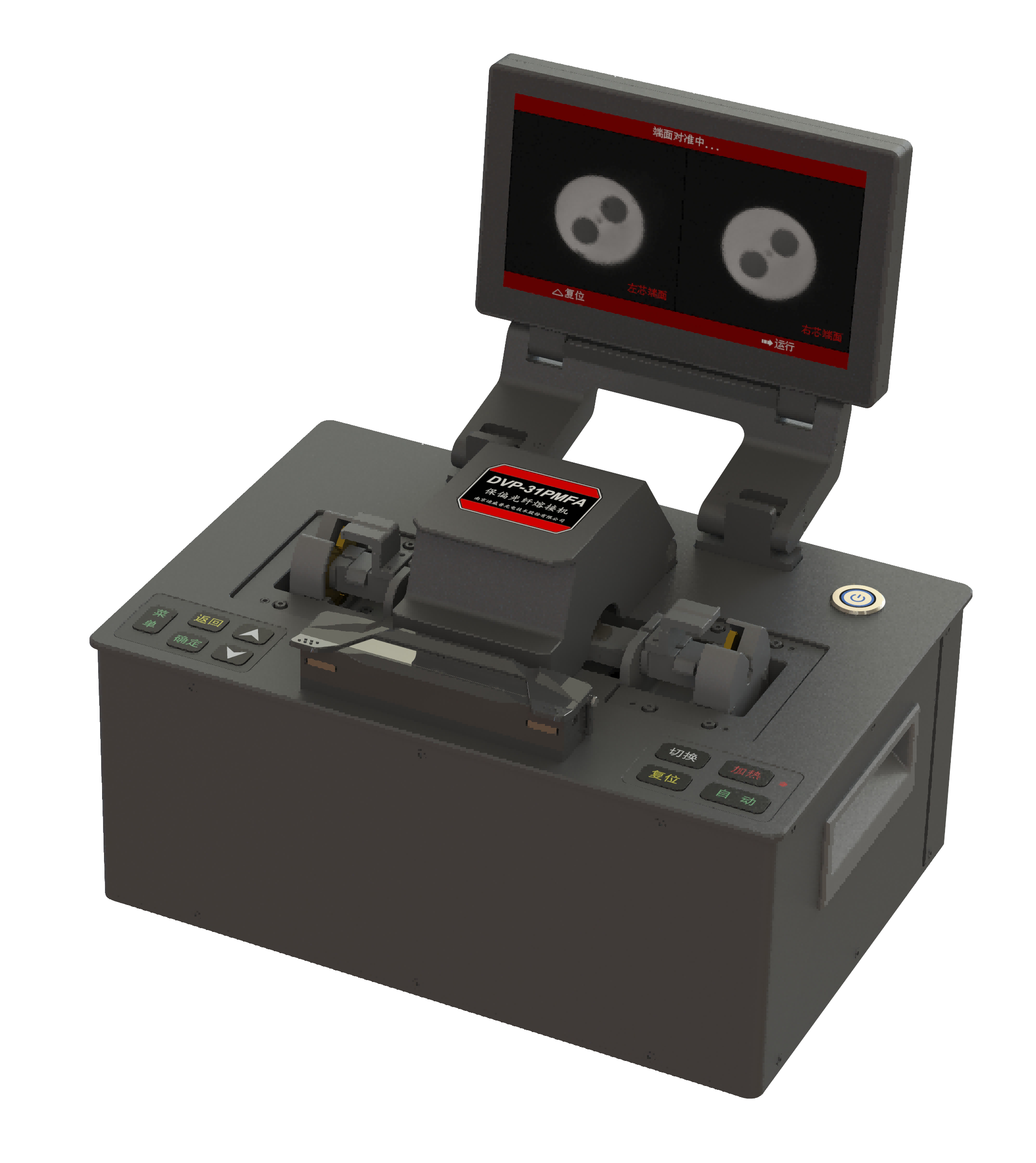
In polarization-maintaining fusion splicers, the alignment process goes far beyond simple core matching. It relies on advanced imaging systems that capture high-resolution views of the fiber ends from multiple angles, typically using LED or laser illumination combined with microscopic optics. These systems detect subtle variations in the stress-applying parts or elliptical core structures unique to PM fibers, allowing the splicer to calculate precise rotational and lateral adjustments. Without such detailed feedback, achieving stable polarization extinction ratios would be nearly impossible.
The real sophistication lies in how the equipment interprets birefringence patterns. By analyzing light intensity profiles as the fibers rotate, the splicer can identify the exact angular offset between their slow or fast axes—a critical step because even a fraction of a degree mismatch degrades performance. Powerful servo-driven stages then execute the necessary corrections with sub-micron resolution, often employing closed-loop control to instantly compensate for any drifts caused by thermal expansion or mechanical stress during the alignment sequence.
What distinguishes industrial-grade systems from simpler models is their ability to handle imperfect fiber geometries. Advanced algorithms dynamically adapt to cladding irregularities or minor core eccentricities, shifting focus from idealized models to real-world fiber characteristics. The result is a consistently low splice loss and high extinction ratio, even when working with less-than-perfect PM fiber batches—a testament to how far alignment technology has progressed beyond the days of manual tweaking and guesswork.
Achieving Sub-Micron Accuracy: The Role of Advanced Imaging and Feedback
Pushing manufacturing tolerances below a single micron isn’t simply a matter of having precise machinery—it hinges on the ability to see and react to what’s actually happening during the process. Advanced imaging systems, such as high-resolution optical microscopes combined with laser interferometry, now capture surface details and dimensional data in real time, turning what was once guesswork into an exact science. This visual stream is immediately fed to motion controllers that compare every frame against the digital model, catching deviations far smaller than a human operator ever could.
The feedback loop is where the magic of sub-micron control really takes shape. Even the most rigid machine tools drift subtly as temperatures fluctuate or tooling wears down. By continuously measuring workpiece features and feeding that data back into the control system, actuators can make nanometer-scale adjustments on the fly. It’s a dynamic, self-correcting conversation between the imaging hardware and the motion platform—one that keeps the process locked onto target despite environmental noise.
What sets today’s solutions apart is the fusion of multiple imaging modalities within a single feedback architecture. Combining confocal microscopy for height mapping with interferometric encoders for lateral positioning, for instance, gives a richer picture of both form and finish. This layered approach not only tightens accuracy but also enables in-situ quality assurance, allowing manufacturers to validate components as they’re being made—eliminating the need for downstream inspection stations and dramatically reducing scrap rates.
Optimizing Splice Parameters to Preserve Extinction Ratio
When working with polarization-maintaining fibers, the splice between two sections can easily degrade the extinction ratio if not carefully controlled. Even slight angular misalignment during alignment can cause coupling between polarization axes, reducing the ER from a pristine 30 dB down to less than 20 dB. It's not just about hitting the lowest loss; the real challenge is ensuring the stress rods or elliptical cladding features are perfectly matched in orientation. I've found that performing a slow, manual alignment in the yaw axis while monitoring the ER in real time often yields better results than relying solely on loss-optimization algorithms.
Temperature and pressure settings at the splice point play a surprisingly large role. If the arc power is too high, the stress-applying parts can melt and diffuse asymmetrically, permanently distorting the polarization characteristics. Conversely, too little heat results in an incomplete fusion with high backreflection, which can create internal interference effects that masquerade as poor ER. A good rule of thumb is to start at a lower power than the standard single-mode recipe and increase by small increments while checking the cross-talk level after each test splice. Equally important is the fiber clamping angle—some splicers allow you to rotate the fiber in sub-degree steps, and that precision is essential when you're trying to hit an ER of 30 dB or more.
Post-splice verification is another area where many overlook easy gains. Measuring the extinction ratio while applying slight tension to the fiber can reveal stress-induced birefringence issues that aren't obvious in a relaxed state. If the ER drops under tension, it's often a sign that the splice zone has created a localized stress point, and you may need to re-optimize the arc duration or push the fibers together more gently during the hot-push phase. In our lab, we also keep a log of every splice parameter tweak—electrode condition, humidity, cleaning method—because these small variables accumulate and can shift the optimal settings over the course of a day. It's tedious, but that level of attention is what separates a consistently high extinction ratio from one that creeps downward with each subsequent splice.
Real-World Performance: Case Studies in Precision Splicing
In a high-volume fiber optic network upgrade across a sprawling metropolitan area, precision splicing techniques were put to the test under demanding field conditions. Technicians working along congested utility corridors encountered frequent alignment challenges due to vibration from heavy traffic and micro bends introduced by older conduit systems. Despite these obstacles, the integration of advanced core alignment fusion splicers with real-time profile adjustment yielded an average splice loss of just 0.02 dB, well below the project’s maximum acceptable threshold. This consistency not only accelerated the deployment timeline but also reduced the need for costly rework and troubleshooting later on.
Various splicing methods were evaluated during a long-haul submarine cable installation spanning several thousand kilometers. The project demanded extraordinary reliability since any signal degradation across multiple splice points would compound over the immense distance. Here, active clad alignment splicers, combined with in-situ OTDR testing at every joint, provided immediate verification and allowed crews to re-splice immediately if a result strayed from the tight loss budget. The data revealed that meticulously controlled cleave angles and pristine fiber end-face preparation were the dominant factors in achieving lab-grade performance in a shipboard environment, where salt mist and constant motion normally complicate operations.
Rolling out fiber-to-the-home in a region dotted with challenging terrain, from rocky hillsides to flood-prone lowlands, further highlighted the real-world advantages of precision splicing. Self-contained, weather-sealed splicing rigs enabled field crews to maintain consistent performance across temperature swings and high humidity. By pairing these ruggedized machines with automated electrode cleaning routines and calibrated heat shrink ovens, the team managed to keep failure rates at junction closures below 0.1% over the first year of service. These results underscore how tailored equipment choices and disciplined on-site protocols turn theoretically achievable splice specs into practical, durable connections that network operators can bank on.
Future Trends in PM Splicing Technology: Automation and Beyond
The relentless pursuit of precision and efficiency in polarization-maintaining fiber splicing is ushering in a new era where automation takes center stage. No longer confined to manual alignment under microscopes, core alignment splicers equipped with machine vision now interpret fiber geometries in microseconds, adjusting rotational and lateral alignment with sub-micron accuracy. This shift isn't just about speed—it’s about making polarization extinction ratios of over 30 dB achievable in field conditions where human dexterity once imposed limits. As these platforms integrate real-time feedback loops, they learn from each splice, gradually building a collective intelligence that anticipates and compensates for environmental variables like temperature or vibration.
Beyond mere automation, the next wave is characterized by intelligent diagnostic layers that predict splice degradation before it manifests. Embedded sensors and spectral analysis tools monitor splice loss and polarization crosstalk continuously, feeding data into predictive models that schedule maintenance only when truly needed. This condition-based approach avoids unnecessary interventions and extends the operational life of critical links in undersea cables, fiber optic gyroscopes, and quantum communication networks. The technology is evolving from reactive to prescriptive, enabling systems that not only alert operators to anomalies but also recommend corrective actions based on historical performance patterns.
Looking further ahead, the fusion of PM splicing with photonic integrated circuits and additive manufacturing techniques promises to redefine what’s possible. Researchers are exploring in-situ splicing within 3D-printed fiber optic assemblies, where stress rods and core geometries are manipulated during the print process itself. This could lead to tamper-proof, monolithic sensing skins for aerospace structures or biomedical implants with embedded polarization-maintaining pathways. Meanwhile, the miniaturization of splicing modules onto chip-scale platforms hints at a future where alignment, fusion, and verification all happen within a single photonic chip, blurring the line between splicing and component fabrication.
FAQ
PM fiber is built with built-in stress elements that create a strong birefringence. This locks the polarization state of light traveling through it, unlike regular single-mode fiber where polarization drifts unpredictably.
Even a slight angular mismatch between the stress rods of two fibers can cause cross-coupling, leaking light from one polarization axis to the other. That degrades the polarization extinction ratio and ruins the very property PM fiber is supposed to maintain.
It uses high-resolution side-view cameras combined with advanced image processing that identifies not just the core but also the stress-applying parts. Active core alignment and rotation stages then precisely orient the fibers before the arc fuses them.
Polarization extinction ratio is the big one, usually targeted above 30 dB. But you also need low insertion loss, typically under 0.1 dB, and high tensile strength to ensure the joint survives real-world handling.
A splice that maintains high PER means your system won't suffer from signal fading or drift over temperature cycles. It also eliminates the need for frequent realignment or replacement, cutting down operational headaches.
Yes, the best models adapt automatically. They recognize the different stress rod geometries through the imaging system and adjust alignment algorithms accordingly, so you don't need separate machines.
It's the precision of the rotational alignment and the feedback loop. Professional units measure PER in real time during the alignment process, not just after, and they can correct sub-micron angular errors that cheaper splicers ignore.
Conclusion
Achieving perfect alignment in polarization-maintaining (PM) fiber splicing demands more than standard core matching—it requires precise rotational orientation of the fiber's stress rods or elliptical core to preserve the polarization state. Without sub-micron accuracy, even minor angular mismatches devastate the extinction ratio, rendering the link useless for high-speed coherent communications or interferometric sensing. High-quality PM fusion splicers tackle this by integrating active core-alignment mechanics with advanced imaging systems. Side-view cameras and high-resolution pattern-recognition algorithms continuously track the stress-applying features, feeding real-time data to motorized stages that rotate and align the fibers while an auto-focus feedback loop compensates for thermal drift and microscopic surface irregularities. This harmonious interplay of optics, electronics, and ultra-fine motion control routinely achieves angular alignment within 0.1 degrees.
Beyond alignment, optimizing splice parameters is critical to maintaining a high extinction ratio—typically exceeding 30 dB in field installations. Programmable arc discharge profiles, tailored to fiber geometry and dopant composition, minimize core deformation and stress redistribution at the joint. Real-world deployments, from submarine gyroscopes to distributed acoustic sensors, demonstrate long-term stability and low loss below 0.05 dB. Looking forward, the technology is embracing higher levels of automation: machine learning models predict ideal splice recipes from a single pre-fuse image, robotic handlers eliminate manual fiber loading, and integrated interferometric inspection verifies extinction ratio on the fly. These innovations not only accelerate network assembly but also make PM splicing accessible to less specialized crews, pushing the boundaries of what is achievable in polarization-sensitive applications.
Contact Us
Contact Person: Mr XU
Email: [email protected]
Tel/WhatsApp: 86-25-85582828
Website: https://www.dvp.cn/en/