
EMI Filter Supplier Delivering High-Performance Noise Suppression Components
2026-10-14
Electrical noise is the silent killer of modern electronics, but it doesn’t have to be. When interference threatens your design, you need more than a generic fix—you need components that actually perform. That’s where DOREXS comes in. As a dedicated EMI filter supplier delivering high-performance noise suppression components, we help engineers silence interference at the source. Ready to see how clean your signals can get?
How EMI Filters Prevent Signal Degradation in Dense Circuit Layouts
In dense PCB layouts, traces run close together, allowing high-frequency switching noise to couple through parasitic capacitance and mutual inductance. This crosstalk and conducted emissions ride on top of intended signals, raising the noise floor and causing bit errors or timing jitter. EMI filters placed at input/output ports or on power rails block these unwanted components before they can spread through the circuit.
A typical filter uses series inductors or ferrite beads to present high impedance to RF currents while passing DC and low-frequency signals, along with shunt capacitors that divert noise to ground. The corner frequency is set below the offending harmonics so only clean baseband signals reach sensitive nodes. In tightly packed boards, this localized filtering is often more effective than relying on shielding alone because it addresses noise at the point where it originates.
Differential-mode and common-mode filtering also target specific coupling paths. Common-mode chokes cancel noise currents that travel in the same direction on both lines, a frequent problem in dense layouts with shared return planes. By suppressing these modes, filters reduce signal distortion and packet loss, even when components sit only millimeters apart.
Component Characteristics That Separate Robust Noise Suppression from Fragile Filters
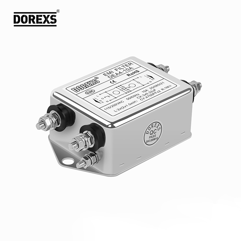
The line between a noise suppression circuit that holds up in the field and one that crumbles under real operating stress often comes down to component choices, not just filter topology. Tight tolerance resistors and capacitors with low voltage coefficient prevent drift in cutoff frequencies. For example, using a C0G or film dielectric in critical filter stages avoids the capacitance loss that plagues X7R ceramics under DC bias. Similarly, resistors with low temperature coefficient keep the damping characteristics stable across extremes. Fragile designs frequently substitute cheaper parts with wide spec spreads, accepting a nominal response that no longer holds when board temperature shifts or supply rails sag.
Magnetic components reveal another clear split. Inductors and ferrite beads in robust noise suppression are selected with headroom on saturation current and self-resonant frequency. A common-mode choke that saturates at 20% above rated line current may work in a lab test but collapse under inrush surges or transient loads. High-quality suppression parts also specify stable permeability over the expected temperature range, whereas fragile filters often use uncharacterized or undersized ferrites that heat up and lose impedance exactly when needed. The difference is measurable in conducted emissions before and after thermal soak.
Mechanical and environmental resilience further separates the two. Robust filters account for coefficient of thermal expansion mismatches between large ceramic capacitors and the PCB, using flexible terminations or smaller case sizes to avoid microcracks. Conformal coating, high-reliability solder joints, and derated voltage ratings help suppress not just electrical noise but also the slow degradation that turns a functional filter into a fragile one after hundreds of thermal cycles. Filters built from components pushed to their datasheet limits may pass initial qualification yet fail in automotive, industrial, or outdoor installations where vibration and humidity are constant. Ultimately, component selection—rather than circuit design alone—determines whether a noise suppression network stays robust or becomes fragile.
Material and Winding Techniques That Shift Filter Behavior at High Frequencies
Core material selection plays a decisive role in high-frequency filter performance. Ferrite cores, for instance, exhibit a rapid drop in permeability above a few hundred kilohertz, leading to reduced inductance and shifting the filter's cutoff frequency upward. Powdered iron and sendust cores retain better high-frequency characteristics but introduce higher losses that can dampen resonant peaks. Nanocrystalline materials offer a compromise, maintaining permeability into the megahertz range while keeping core losses manageable, which helps preserve the intended filter shape without excessive attenuation in the passband.
Winding techniques directly influence parasitic elements that become critical at high frequencies. A single-layer solenoid minimizes interwinding capacitance, allowing the inductor to behave more like a pure reactance well into the RF region. In contrast, multi-layer or random windings create significant distributed capacitance that can form unintended parallel resonances, causing sharp notches or peaks in the filter response. Techniques such as bank winding, progressive winding, or using spaced turns reduce this capacitance, while bifilar or sectionalized windings can deliberately introduce coupling to shape the high-frequency roll-off.
Combining the right material with an appropriate winding scheme yields filters that maintain predictable behavior well beyond the nominal design range. For example, a high-frequency common-mode choke built on a low-loss ferrite toroid with a single-layer spaced winding will exhibit minimal leakage inductance and low parasitic capacitance, preserving attenuation up to several hundred megahertz. Conversely, a filter intended to suppress a specific narrowband harmonic might exploit a multi-layer winding on a high-permeability core to create a self-resonant notch, shifting the filter's stopband precisely where needed. The interplay between these choices allows engineers to fine-tune high-frequency response without adding extra components.
Design Considerations for Filter Integration in Tight Power Enclosures
Packing filters into compact power enclosures demands more than just checking physical dimensions. Thermal rise becomes the first real obstacle, since filters dissipate heat and tight spaces restrict airflow. Placing a filter too close to electrolytic capacitors or other temperature-sensitive parts can silently degrade reliability, even if the enclosure stays within rated ambient. A practical approach is to map hot spots with a simple thermocouple run before finalizing mounting points, then bias filter placement toward cooler inlet regions or add small vent slots that don't compromise shielding.
Magnetic coupling is another silent killer in dense layouts. Inductors and common-mode chokes radiate stray fields that can induce noise into nearby signal traces, gate drive circuits, or even the filter's own sense lines. In tight power enclosures, the usual rule of leaving one core diameter of clearance often fails simply because there is no room. Twisting differential pairs, keeping filter input and output leads on opposite sides of the chassis, and using shield plates made of high-permeability material between the filter and sensitive nodes are all workable fixes that depend less on distance and more on orientation.
Mechanical stress also deserves attention. Filters bolted directly to a thin steel wall can transfer vibration from cooling fans or external machinery into solder joints and ceramic capacitors. Over time, this leads to micro-cracks and intermittent failures that are hard to reproduce on a bench. A resilient gasket or a small standoff bracket not only dampens this vibration but also helps maintain galvanic contact for low-impedance grounding. The trick is to keep the ground path short and wide while allowing a tiny bit of flex, something many designers overlook until a field return lands on the desk.
Customization Routes for Unusual Voltage Spikes and Conducted Emissions
Handling unusual voltage spikes and conducted emissions often requires moving beyond off-the-shelf filtering. A practical customization route starts with a detailed signature analysis of the disturbance: capturing the spike's rise time, amplitude distribution, and repetition pattern, as well as the spectral profile of conducted noise across the relevant frequency band. This data feeds directly into the selection of non-standard component values or topologies—such as asymmetric LC stages, dissipative snubbers tuned to specific ringing frequencies, or ferrite materials chosen for their loss characteristics at the observed emissions peak.
Another route involves tailoring the physical layout and grounding scheme rather than adding more components. For example, isolating a noisy switching node with a dedicated return path or repositioning a high dv/dt trace away from sensitive input lines can reduce both radiated coupling and conducted emissions at the source. When spikes are irregular and load-dependent, a dynamic approach may be justified: using a small sensing circuit to actively damp only the problematic transients while leaving normal operation unaffected. This kind of selective intervention avoids the efficiency losses and bulk of a broadband filter.
Finally, custom magnetics offer a focused path for both spike suppression and conducted emission control. A carefully specified common-mode choke with intentional leakage inductance can double as a differential-mode filter element, saving space and improving high-frequency attenuation. For unusually high voltage spikes, integrating a clamping winding or deliberately saturating core behavior into the transformer design can limit peak voltages before they reach downstream electronics. These routes all require close collaboration between the circuit designer and the magnetics or filter vendor, but the result is a solution matched to the actual offending waveform rather than a generic attempt to cover every contingency.
Durability Testing Insights That Reveal Real-World Filter Performance
Lab tests that only measure clean-element efficiency miss most of what matters when a filter is bolted into a machine and left to work for months. Real-world durability comes down to how well the media holds up under repeated cold starts, heat soaks, vibration from rough roads or hydraulic pulses, and a steady diet of contaminated fluid. We have found that filters with high initial efficiency can lose more than a third of their particle retention after a few hundred thermal cycles if the pleat bonds are not stabilized. Watching the pressure drop curve during a 1,000-hour dirt-loading run tells you more about field life than any single-pass efficiency number.
A sharper distinction shows up between failure that is quiet and failure that is sudden. A filter that slowly loads and goes into bypass may protect the system for a long time, while another with a weak seam lets a burst of unfiltered fluid through under a cold-start pressure spike. Durability testing should include cyclic flow interruptions, not just steady-state flow, because that is what makes adhesive joints flex and fatigue. When you combine dust loading with vibration and temperature swings, you start seeing which designs survive the messy conditions that bench tests ignore.
FAQ
The core difference is in how we handle the mid-band attenuation curve. We pair a high-permeability ferrite with a smaller nanocrystalline stage, so insertion loss doesn’t dip sharply after 5 MHz the way it does with many standard filters. For a customer running variable-frequency drives, that translates to fewer random trips and cleaner encoder signals on the same ground plane.
Yes, we’ve done low-profile designs down to 6.5 mm without sacrificing current handling. The trick is using flat-wire windings instead of round magnet wire, which reduces the air gap losses and lets us spread the same inductance over a wider footprint. We usually ask for a 3D step file of the enclosure early so the mechanical team can catch clearance issues before the first prototype.
Every production lot goes through a network analyzer sweep from 150 kHz to 1 GHz, not just the standard CISPR band. We also do a 500-hour biased humidity test on a sample from each batch. For hot-swap or high-vibration installations, we add a random vibration profile at 2.4 g RMS for 30 minutes per axis. If a unit drifts more than 0.5 dB from the golden sample, the whole lot gets quarantined.
The largest share goes to medical imaging equipment—CT gantries and MRI power supplies—where even low-level conducted noise can degrade image quality. We also supply a fair number of server power racks, electric vehicle charging modules, and a handful of aerospace ground-support systems. The aerospace work is smaller in volume but pushes us hardest on thermal cycling and documentation.
We rate the standard line for continuous operation at 105°C case temperature, with a 125°C short-term peak for 30 minutes. That comes down to using a polyimide film in the capacitors and a high-temperature epoxy that doesn’t crack during thermal shock testing. We’ve seen competitors use generic mylar that starts to delaminate around 90°C, which is where leakage current begins to creep up.
Most of our single-stage filters give you at least 40 dB of common-mode attenuation at 1 MHz, and the two-stage versions push past 70 dB from 300 kHz to 30 MHz. Differential-mode noise is a little harder to generalize, but we usually target 20–30 dB in the same band. The important part is that the curves are consistent from unit to unit—our data sheet shows a typical spread of less than 2 dB, not the 6–10 dB you sometimes see on low-cost parts.
We can, but we’re careful not to turn it into a guessing game. The first step is usually a near-field probe scan on your board to map where the dominant sources are, then we run a quick simulation with your power distribution network. After that we’ll recommend either a filter topology change or a shielding/grounding fix. In about two-thirds of cases, the filter alone solves it; the rest need a change in layout or cable routing, which we’ll point out in the report.
If you can approve a design within five working days, we can usually ship first-article samples in three weeks. For a production run of 2,000 to 5,000 pieces, expect another six to eight weeks after sample sign-off. Rush options exist—we once turned a 1,000-unit order in 18 calendar days—but that depends heavily on whether the cores and custom bobbins are already in stock or need to be machined.
Conclusion
Working with an EMI filter supplier that understands dense circuit layouts means more than swapping in a generic component. Their filters stop signal degradation by containing conducted noise before it couples into neighboring traces, keeping high-speed data paths clean. The difference shows in the construction: robust units use tightly controlled core materials and winding geometry to maintain impedance at frequencies where fragile filters drift or saturate. In compact power enclosures, every millimeter counts, so the best designs treat the filter as part of the thermal and mechanical stack, not an afterthought.
When voltage spikes or unusual conducted emissions appear, a capable supplier shifts from catalog parts to tailored solutions—adjusting capacitance, adding damping stages, or reworking lead placement to hit a specific attenuation curve. Durability testing then separates marketing claims from field reality: thermal cycling, vibration, and surge exposure reveal whether a filter keeps its performance over years, not just on a datasheet. The result is a noise suppression component that delivers predictable, long-term operation rather than a fragile patch. That level of engineering support turns a standard procurement item into a genuine design advantage.
Contact Us
Contact Person: Eric
Email: [email protected]
Tel/WhatsApp: 8618117837140
Website: https://www.emcdorexs.com